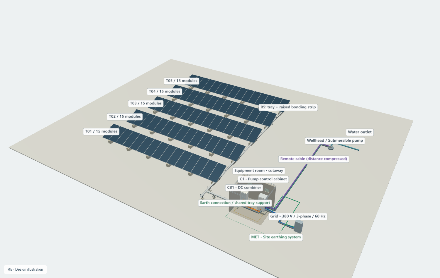
Five tables · 15 modules per tableRotate · Explore components · Follow cable routes
01 / SYSTEM VIEW
5systemsIndependent pumping systems
26tablesMounting tables across five systems
390positionsMechanical module positions
120km/hStructural design target
EXPLORE THE SYSTEM
See how it all connects.
Switch views to explore each part of the system. The 3D example shows five single-row tables serving one 30 kW pump.
Loading the 3D view...
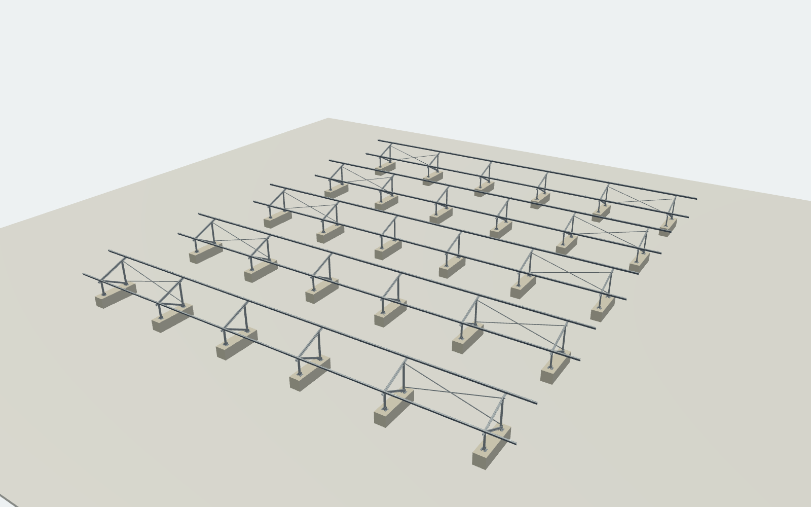
Updated supplier ST5 drawing UI-260910-063-01, dated 11 September 2026. Five 1 × 15 tables carry 75 modules (48.75 kWp at 650 W). Foundation geometry is 1500 × 400 × 400 mm; finished ground level, embedment and site spacing remain to be confirmed. Connection details and cabinet wiring are illustrative.
The current proposal combines the full system with independent supports, bottom perforations and conduit-entry clearances. View dimensions and installation details. Geometry is shown for review; structural and anchor capacity remain to be confirmed.
PROJECT CONFIGURATION
One project. Five pumping systems.
Each supplier ST5 table supports one row of 15 modules. Four, five or six identical tables serve each pumping system. Each system retains its own DC combiner and control cabinet.
Supplier rail length per table17.60 mEnd-to-end rail length, with 17.262 m across the modules. Foundations, shading clearance and access determine the site footprint.
Pump rating
Quantity
Tables / system
Positions / system
22 kW
1
4
60
30 kW
2
5
75
37 kW
2
6
90
Project total
5 systems
26 tables
390
60 modules: 4 × 15. 75 modules: 5 × 15. 90 modules: 6 × 15. The project remains 390 modules / 253.50 kWp at 650 W. The illustrated 75-module system retains five 15-module string routes; final electrical sizing follows the confirmed module and GD170 limits.
WATER, WHEN IT IS NEEDED
Choose how your farm is supplied.
Interactive demonstration only
DAYTIMESolar pumping
◐NIGHTWaiting for sunlight
The maintained selection permits operation to resume the next day. Water-level, temperature and fault protection take priority.
Protection takes priority. Low water, a full tank, faults or overtemperature stop the pump as defined by the control logic. The design uses a 50°C actual upper air-temperature limit at the drive inlet, a red alarm and manual reset after cooling. Continuous operation at 55°C ambient is not specified.
STRUCTURE & MATERIALS
A practical mounting arrangement.
Standard sections and matched module clamps. Manufacturing drawings define dimensions, holes and assembly details.
01
Supplier ST5 · S350GD
C80 × 40 × 10 · t 1.8 mm
Rails and inclined beams follow the supplier drawing. Posts and diagonals: C60 × 40 × 10 × 1.8 mm.
02
Six support frames per table
3,150 mm frame spacing
Six 1500 × 400 × 400 mm concrete blocks per table, each supporting the front and rear legs. L140 base components are retained. The revised proposal uses one common U-anchor SKU for PV legs and tray supports; the new anchor arrangement requires verification.
03
Rear bracing and accessories
U21 × 1.5 mm · Standard clamps
Rear X bracing at both end bays. Coating specification and matched module-clamp details follow the final supplier documentation.
Shared front/rear concrete foundations
The updated drawing shows six 1500 × 400 × 400 mm blocks per table. Each block supports both legs of one frame. The 500 mm module clearance is shown relative to the foundation top. Final ground level, embedment, reinforcement and bearing capacity require site confirmation.
FROM ARRAY TO PUMP
Follow the power from array to pump.
01
PV array
Positive and negative cables paired by string
02
DC combiner box
Five protected string inputs combined
03
Pump control cabinet
PV/grid transfer and motor drive
04
Submersible pump
Separate motor cable and protective earth
Covered perimeter cable tray
Proposed main tray: 200 × 100 × 2 mm with plain removable lids and adjustable stainless band clamps. The tray and 40 × 4 mm candidate earth strip share independent welded supports anchored to the existing end plinths, with a 484 mm bearing level. Lid bands and tray-to-support fasteners are separate. Dedicated slotted bottom fixings and smaller auxiliary perforations are shown. Five cable pairs collect from five tables along one side. Short stainless flexible conduits attach to the existing rear posts and enter the tray through matched fittings; no independent drop support is added. Final tray size, thermal derating, supports and cable quantities follow the actual route and cable schedule.
Short module jumpers descend beside each row-end rear leg and terminate through crimp lugs directly on the raised common strip beside the tray. No intermediate angle adapter or branch plate is used. The strip returns to the site earthing connection. This above-ground bonding route does not replace an earth electrode. Conductor material, section and terminal compatibility remain to be confirmed.
Accessible control cabinet
The DC combiner and pump control cabinet stand side by side in a proposed concrete equipment room. Explore the door controls, internal functional zones and side ventilation. Grid input and pump output follow separate protected routes, with suitable entry glands and edge protection.
ENGINEERING, WITH TRACEABILITY
Engineering behind the proposal.
Engineering documents will be uploaded as their R5 revisions are completed. The current 3D proposal is provided for arrangement review and confirmation.
STRUCTURAL LOAD REPORT120km/h
Wind design target
The R5 structural load report is currently being prepared. It will assess the mounting members, connections, anchors and foundations against the confirmed site conditions and design criteria.
UNDER PREPARATION · REPORT WILL BE UPLOADED WHEN COMPLETED
Member strength and stability
In progress
Structural assessment of the current R5 mounting arrangement is being prepared.
Connections and deformation
In progress
Connection forces, restraint assumptions and deformation limits will be checked in the R5 report.
Foundation bearing and stability
Site data required
Final verification will use the confirmed ground level, soil conditions, reinforcement and foundation details.
R5 structural load report
Under preparation
The completed report will be uploaded here after engineering review.
Standards and scope Design reference, not a certificate