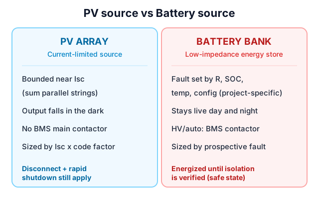
A solar array and a battery bank both sit on the DC side of a system, so it is tempting to protect them the same way. That is a mistake. A PV array is a current-limited source whose output collapses in the dark; a battery is a low-impedance energy store that can deliver very high fault current regardless of sunlight, and stays live until it is deliberately isolated.
Those differences change fuse and breaking-capacity requirements and explain why high-voltage or automatically controlled BESS commonly use BMS-commanded contactors and pre-charge, while passive PV strings use a different switching and disconnection architecture.
PV source vs battery source (protection-relevant)
| Property | PV array (string / combiner) | Battery bank (BESS DC) |
|---|---|---|
| Source type | Current-limited (I-V curve) | Low-impedance voltage source |
| Fault current ceiling | Bounded by configured PV source contribution; at a combiner include parallel-string Isc | Set by internal R, SOC, temperature, config, loop |
| Behavior in the dark | PV source contribution falls with irradiance; conductors may remain energized by other connected sources | Unchanged, stays live |
| Live until isolated? | PV contribution is irradiance-dependent; verify isolation from every connected source | Treat as energized until isolation is verified and the system is brought to a defined safe state |
| BMS-commanded main contactor? | Not used (PV disconnect and rapid-shutdown still apply) | Common in HV / automated BESS; small LV may differ |
| Needs pre-charge? | Not typically at the passive string level; inverter or PCS architecture may differ | Often in HV / automated; LV depends on inverter and BMS |
| Sizing basis | Isc with code factors | Prospective fault current plus interrupting rating |
Illustrative comparison for engineering education; project protection must be sized from actual system data by the project engineer.
How does a PV array behave under a fault?
A photovoltaic module is fundamentally current-limited by its I-V curve. Its short-circuit current (Isc) is normally only moderately higher than its maximum-power current (Imp); the actual ratio is module-specific and must be taken from the module datasheet. Whatever the ratio, a single module or independent string is current-limited to about its Isc for the applicable irradiance, temperature and test conditions, and cannot be driven far above that by a short.
At a combiner the fault-point current is not one string Isc. The reverse contribution of the other parallel strings must be summed, so distinguish single-module Isc, single-string Isc, and the total parallel-string contribution at the fault location.
This is why PV codes design maximum current around Isc: for example under the 2023 or 2026 NEC 690.8(A), the maximum current is the sum of parallel-module Isc times 125 percent, and 690.8(B) then applies a second 125 percent continuous-load factor to conductor sizing. The edition adopted in the project jurisdiction governs, and specific device selection must be checked against it. The array also stops producing when irradiance falls, so a faulted string de-energizes at night. That is a property of the array as a source, not a safety guarantee: series-connected batteries or other sources on the same DC bus can keep conductors live, and building PV still has its own disconnect and rapid-shutdown obligations.
How does a battery bank behave under a fault?
A battery is the opposite: a low internal-impedance voltage source. Prospective fault current is set by cell and pack internal resistance, state of charge, temperature, series and parallel configuration and loop impedance. It can greatly exceed the normal operating current, but the magnitude is project-specific and must be established from manufacturer data and the actual circuit configuration. Do not use a fixed marketing number such as ten times.
A battery also holds energy chemically. The battery circuit must be treated as energized until isolation has been verified and the system has been brought to a defined safe state under the approved procedure. That is the core reason battery DC distribution needs a means of disconnection that PV racks handle more simply.
Isc, Imp and continuous current: why the distinction matters
For PV, protection is sized from the current-limited source values with code continuous-duty factors. For batteries, the normal operating current tells you almost nothing about the fault duty. You must separately establish the prospective fault current and the required interrupting rating. Conflating rated current with fault current is the single most common battery-BOS sizing error.
When do batteries use contactors and pre-charge, and PV strings do not?
High-voltage and automatically controlled BESS commonly use a BMS-commanded main contactor, opened on fault, over-temperature or command, and a pre-charge sequence (resistor plus contactor) to limit inrush when closing onto a capacitive DC link such as an inverter or PCS.
Small low-voltage systems may use a different architecture, relying on the internal BMS, MOSFET switching, a manual breaker, fuses or the inverter internal pre-charge, which must be confirmed from the actual battery and inverter design. A passive PV string does not use a BMS-commanded main contactor. Note this is about the controlled main contactor, not about whether PV needs disconnection at all: PV disconnect and rapid-shutdown requirements still apply per the system and local code.
Contactor vs fuse vs breaker: three different jobs
These are not interchangeable. A contactor is a controlled switching device, opening and closing on command with a limited fault-interrupting role. A fuse is a one-shot fault-current interrupter with a defined time-current and let-through energy characteristic. A breaker is a resettable overcurrent protective device with a defined interrupting rating. Depending on voltage level, system architecture and protection strategy, a battery DC cabinet may use all three, each for its own function; picking one to do another job is where designs fail.
Standards referenced
NEC 690.8 - use the edition adopted by the project jurisdiction. Final protection and device ratings must be verified against manufacturer data and applicable certification documentation.
Verify against official sources (for example the NFPA text and the device certifier records) rather than third-party articles. This page is general engineering information; project protection is confirmed by the project engineer and, where certification applies, the designated NRTL.
FAQ
Is battery fault current really higher than PV fault current?
Usually yes, often by a large margin, but the multiple is project-specific and set by internal resistance, SOC, temperature and configuration. Never quote a fixed number.
Can I reuse my PV DC fuses in a battery system?
Not by default. DC-rated devices may look similar, but battery duty (bidirectional current, higher prospective fault current, different time-current needs) must be checked against the actual device rating and conditions of acceptability.
Does a battery de-energize like a PV array at night?
No. A battery holds energy chemically and stays live until discharged and isolated. Never treat a battery bus as dead without verified isolation.
Does OmniSol design my protection scheme?
OmniSol can source and coordinate project-confirmed BESS DC-side BOS components. Final protection design and device selection remain with the project engineer and designated certification parties.
RFQ details to prepare
- System type: PV source, battery, or hybrid DC bus
- Battery prospective fault current with test conditions
- Module Isc and parallel-string count at the combiner
- DC voltage and required interrupting ratings
- Whether a BMS-commanded main contactor is present
- Destination market and applicable code edition
Avoid these mistakes
- Reusing PV DC fuses in a battery circuit without re-rating
- Treating a battery bus as dead without verified isolation
- Quoting a fixed fault-current multiple such as ten times
- Sizing battery protection from operating current