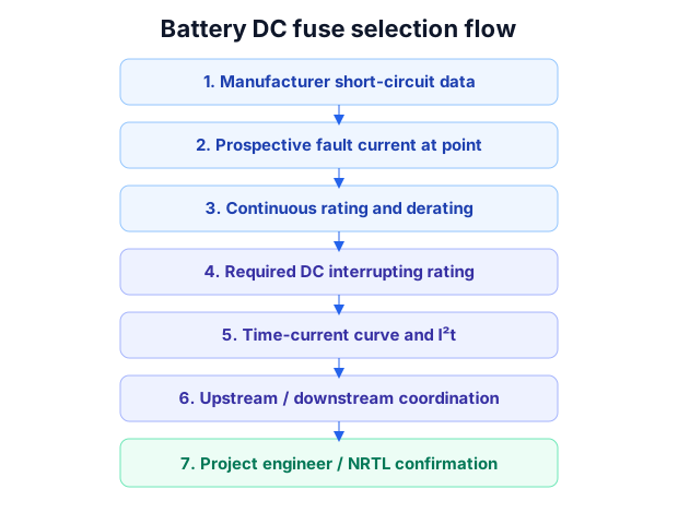
You cannot pick a battery DC fuse from the operating current alone. The fuse must safely interrupt the prospective fault current the battery can actually deliver and coordinate with devices upstream and downstream, while its let-through energy (I²t) must remain within the withstand capability of downstream conductors and components.
This is a framework for the reasoning and the inputs. It is deliberately not a calculator, and explicitly not a final selection, which belongs to the project engineer and certification party.
What inputs do you need before sizing anything?
In priority order: the manufacturer-provided maximum short-circuit current, including its test conditions and duration, the BMS output-protection behavior, contactor state, parallel-cluster contribution and any possible PCS DC-bus feedback. Then system nominal and maximum DC voltage, chemistry and pack internal resistance, state of charge and temperature range, series and parallel configuration, conductor and busbar resistance and length, contact resistances, and the prospective fault current at the point of protection.
Manufacturer-provided short-circuit data and tested protection behavior take priority over simplified internal-resistance estimates. A plain V over R estimate is a screening tool only, not enough to select a fuse on its own.
Why operating current is the wrong starting point
Rated continuous current tells you the fuse must not nuisance-trip in normal use. It says nothing about whether the fuse can interrupt the fault. Sizing from operating current alone routinely produces a fuse with inadequate interrupting rating for the prospective fault current of the battery.
Peak vs steady-state fault current: the time dimension
Battery fault current is not a single number. There is an initial peak governed by the lowest-impedance path, then behavior that changes over milliseconds to seconds as the source and loop respond. Protection must be evaluated against the relevant point in time, not one nominal figure.
How cable, busbar and contact resistance change the answer
Loop impedance limits fault current. Longer or thinner conductors and real contact resistances reduce prospective fault current, but they also affect voltage drop and coordination. These are inputs to the calculation, not afterthoughts.
Interrupting capacity, time-current curves and let-through energy
Three device properties matter: the interrupting or breaking rating must be at least equal to the maximum prospective fault current under the applicable DC voltage and rating conditions; the time-current curve must clear the fault fast enough without nuisance tripping; and the let-through energy (I²t) is the characteristic of the fuse that the downstream conductors, busbars and components must survive. The let-through energy belongs to the fuse; it is the downstream items that must withstand it.
Coordination, and where the framework stops
Where selective coordination is required and technically achievable, the protection scheme should aim to clear the device closest to the fault while minimizing unnecessary upstream interruption. Full selectivity is an ideal target, not something every DC system can fully achieve; it is a coordination study across the DC path, not a per-device choice.
This framework helps you gather inputs and reason about protection. It does not produce a final part number. Final selection is confirmed by the project engineer and, where certification is involved, the designated NRTL, against the actual system configuration.
FAQ
Can I size a battery fuse from the operating current?
No. You select a fuse whose DC interrupting rating is adequate for the maximum prospective fault current under the applicable voltage and rating conditions. Operating current remains one input to the continuous-current rating, together with temperature, duty cycle and applicable derating factors.
Is there one fault-current number for my battery?
No. It varies with SOC, temperature, configuration and loop impedance, and over time within a fault.
Does this give me a final fuse part number?
No. It is a framework; final selection is confirmed by the project engineer and NRTL.
RFQ details to prepare
- Nominal and maximum DC voltage
- Chemistry and pack internal resistance
- State of charge and temperature range
- Series and parallel configuration
- Conductor and busbar resistance and length
- Contact resistances
- Prospective fault current at each protection point
- Required interrupting rating
- Downstream conductor withstand capability
Avoid these mistakes
- Sizing a fuse from operating current only
- Treating fault current as a single number
- Ignoring loop and contact resistance
- Assuming a PV DC fuse transfers to battery duty
- Treating this framework as a final selection