Grounding is the part of a commercial solar BOM that is most often under-specified. The array needs two separate things: equipment earthing (bonding every panel frame and rail so a fault cannot leave metal parts live) and, where required, lightning protection earthing per IEC 62305 or local code. They use different hardware and are checked by different inspectors.
This guide covers the grounding approaches used on commercial rooftop and ground-mount projects, the hardware that implements each one, and what to put in the RFQ so the earthing kit arrives with the racking instead of becoming a site-sourced afterthought.
Rail bonding vs separate earth conductor
Modern racking systems achieve equipment earthing through the rail itself: bonding mid-clamps or WEEB-type washers pierce the anodised layer and create a conductive path from panel frame to rail, so one earth lug per rail row replaces a lug on every panel. For this to be accepted, the racking must be certified as a bonding path — UL 2703 in the US market, or a manufacturer earthing-continuity test report elsewhere.
The traditional alternative — a separate copper earth conductor daisy-chained through a lug on every panel frame — is still specified in some markets and by some EPC standards. It costs more in copper and labour but does not depend on racking certification. Many commercial projects mix the two: rail bonding on the array, a separate conductor from each rail row to the earth bar.
- Rail bonding: needs UL 2703 listing or earthing continuity report, one lug per row
- Separate conductor: 6mm²–16mm² bare or green/yellow copper, lug on every frame
- Ground-mount: piles are not automatically an earth electrode — check soil resistivity and local code
Grounding hardware in a commercial solar BOM
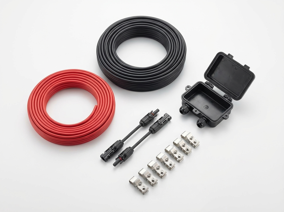
A complete grounding kit for a commercial array typically includes: bonding mid/end clamps or WEEB washers (matched to the rail brand), stainless earth lugs sized for the conductor, splice-joint bonding jumpers (rail splices are not reliable conductors on their own), earth bars or busbars at the combiner position, and — for lightning protection — air terminals, down conductors and earth electrodes per the IEC 62305 risk assessment.
The most common failure we see at QC is mismatched hardware: lugs that do not fit the rail profile, washers specified for a different rail brand, or bonding jumpers missing at every splice. Ordering the grounding kit from the same supplier as the racking removes the compatibility risk.
Compliance by market
USA: UL 2703 covers bonding and grounding of the racking system; NEC 690.43–690.47 governs the equipment grounding conductor and grounding electrode system. Inspectors ask for the UL 2703 listing card and torque specs.
Australia/NZ: AS/NZS 5033 requires equipotential bonding of the array frame; earthing conductor minimum 4mm² copper (6mm² typical), and the earthing system is checked at grid-connection inspection.
EU: EN/IEC 62305 lightning protection risk assessment decides whether the array needs dedicated LPS earthing; equipment earthing follows IEC 60364-7-712. German and Dutch insurers increasingly ask for the 62305 assessment on commercial roofs.
Procurement decision table
| Decision area | Buyer question | Procurement check | Risk control |
|---|---|---|---|
| Product scope | Which product families does this cover? | Solar Mounting Systems, Combiner Boxes, DC Protection | Ordering racking and grounding hardware from different suppliers without checking compatibility |
| Specification input | What must be stated before comparing quotes? | Racking bonding certification (UL 2703 listing or earthing continuity report) | Use the same specification wording across supplier quotes. |
| Commercial input | What makes the quote operationally useful? | Earth conductor size and material per destination-market code | Tie quantity, packing and destination to the same RFQ line. |
| Quality gate | What should be checked before shipment? | Solar Mounting Wind Load Guide | Assuming rail splices provide electrical continuity without bonding jumpers |
BOM and RFQ context
Commercial Solar Grounding Solutions: Hardware & Code Guide is most useful when it is read as a sourcing decision, not only an informational article. The affected product scope normally includes Solar Mounting Systems, Combiner Boxes, DC Protection, Solar BOS Components. A buyer should connect the answer to a live BOM, because cable size, connector rating, protection device choice, box configuration, storage accessories and export packing can change together.
For a procurement guide, the goal is to turn a broad buying question into a repeatable RFQ structure. The buyer should leave with the required product family, specification fields, quality checks and internal links needed to continue into the central products hub. In an RFQ, the minimum inputs should include Racking bonding certification (UL 2703 listing or earthing continuity report), Earth conductor size and material per destination-market code, Bonding jumpers at every rail splice, Earth lugs matched to rail profile and conductor size. These inputs let a sourcing team compare suppliers on the same basis instead of only comparing unit price.
The related follow-up content is Solar Mounting Wind Load Guide, Solar Mounting Standards by Country, DC Protection Selection Guide. Use those pages to validate standards, sizing, inspection and packing before sending a final quote request. The main risk to avoid is: Ordering racking and grounding hardware from different suppliers without checking compatibility Assuming rail splices provide electrical continuity without bonding jumpers
FAQ
Do solar panels need individual grounding lugs on every frame?
Not if the racking is certified as a bonding path (UL 2703 or an earthing continuity test report): bonding clamps or WEEB washers connect each frame to the rail, and one earth lug per rail row completes the path. If the racking has no bonding certification, a separate earth conductor with a lug on every frame is the safe specification.
What size earthing cable does a commercial solar array need?
Typical specifications are 6mm² copper for equipment earthing runs in AU (AS/NZS 5033 minimum is 4mm²), 8–10 AWG per NEC 690.43 in the US, and 6–16mm² in EU projects depending on the fault-current calculation. Lightning down conductors per IEC 62305 are sized separately, commonly 16mm² copper or equivalent aluminium.
Are ground-mount steel piles an acceptable earth electrode?
Sometimes, but never by assumption. Galvanised piles in low-resistivity soil can serve as electrodes where local code allows, but corrosion coupling and soil resistivity must be checked. Most commercial ground-mount designs still install dedicated earth rods or a buried ring conductor and bond the piles to it.