Five 1 × 15 tables combine supplier mounting geometry, module wiring and retention, rear-post flexible conduits, independently anchored tray supports, bonding strip and cabinet interfaces. This 75-module example does not change the 390-module project total.
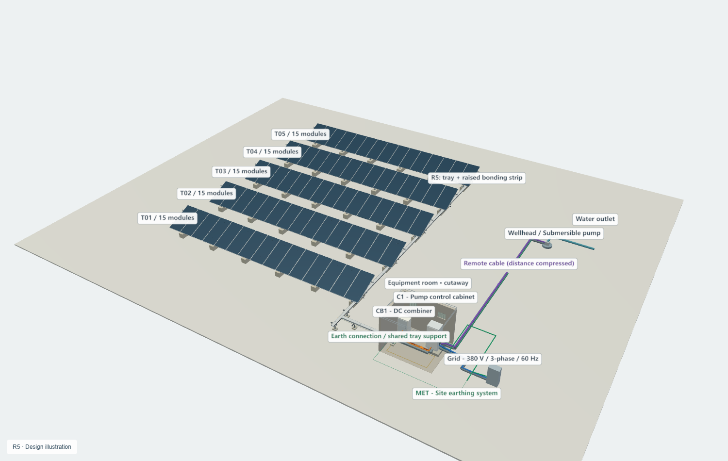
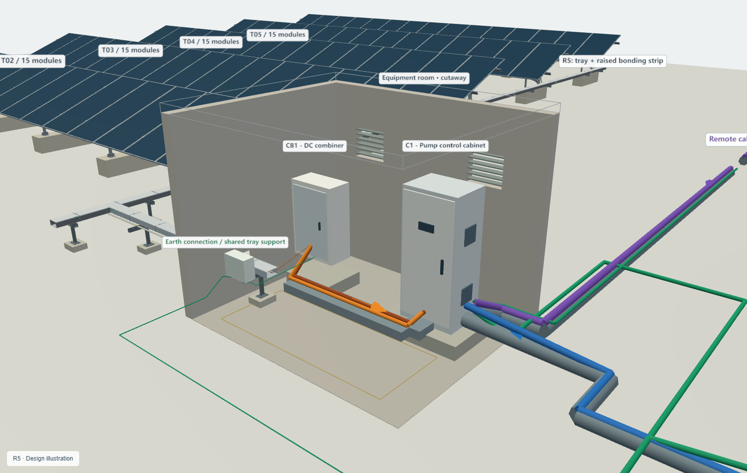
CB1 and C1 now stand side by side, facing the same service aisle, in a concrete-room cutaway. The proposed outside envelope is 3700 × 3100 × 2800 mm (wall height). Roof/front/right walls are omitted from the review view. Ventilation sizing, thermal design, building construction and working clearances remain to be confirmed.
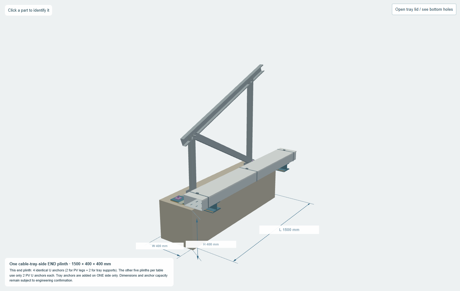
The Foundations view isolates one 1500 × 400 × 400 mm end plinth and one support frame. Only ONE cable-tray-side end plinth per table has four U anchors: two for PV legs and two independent tray-support anchors. The other five plinths each use two PV U anchors. All use one candidate SKU; geometry is unified, but anchor capacity and supplier acceptance are not released. Five illustrated tables therefore contain 60 PV U anchors plus 10 tray U anchors, 70 total. This is the 75-module example, not the whole-project purchasing quantity.
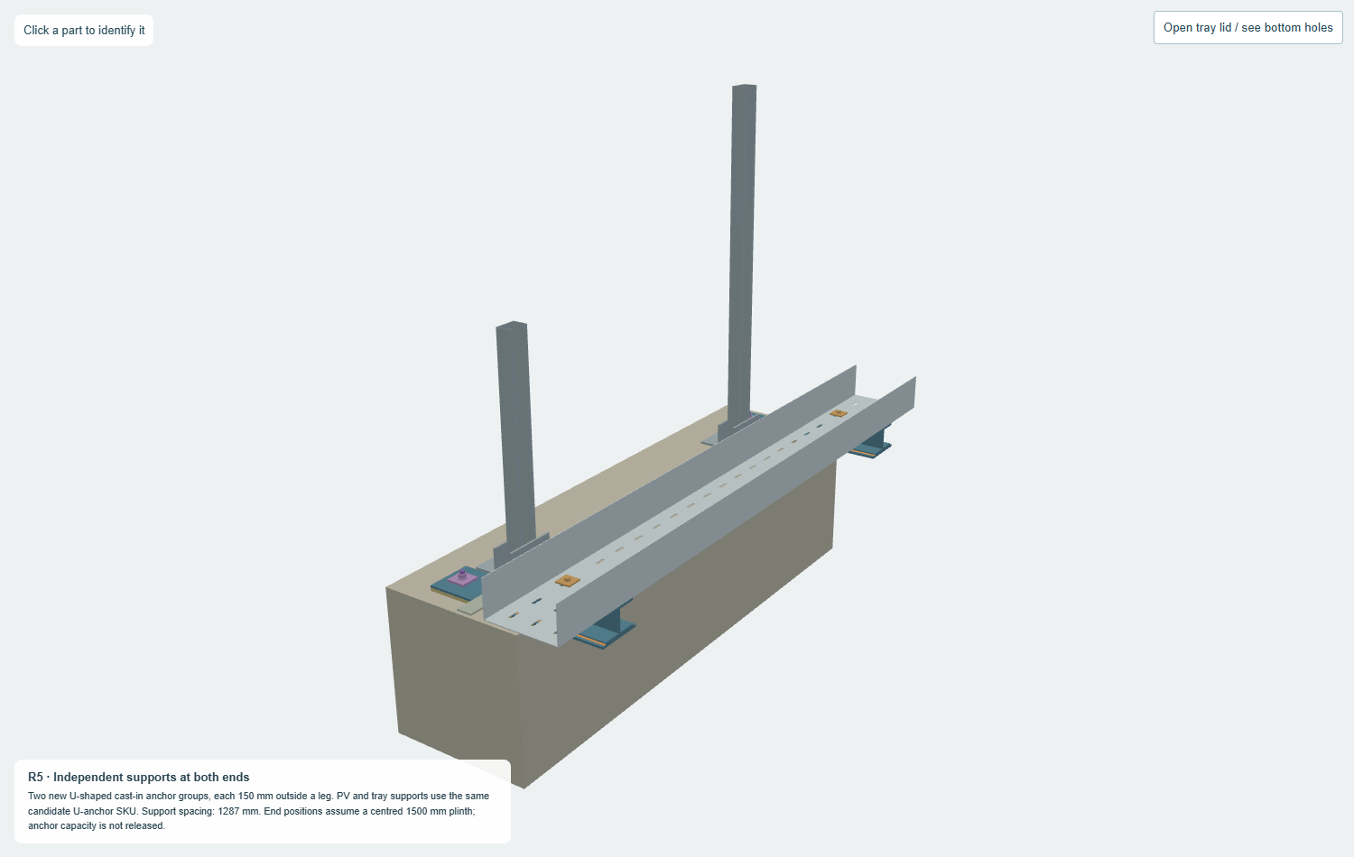
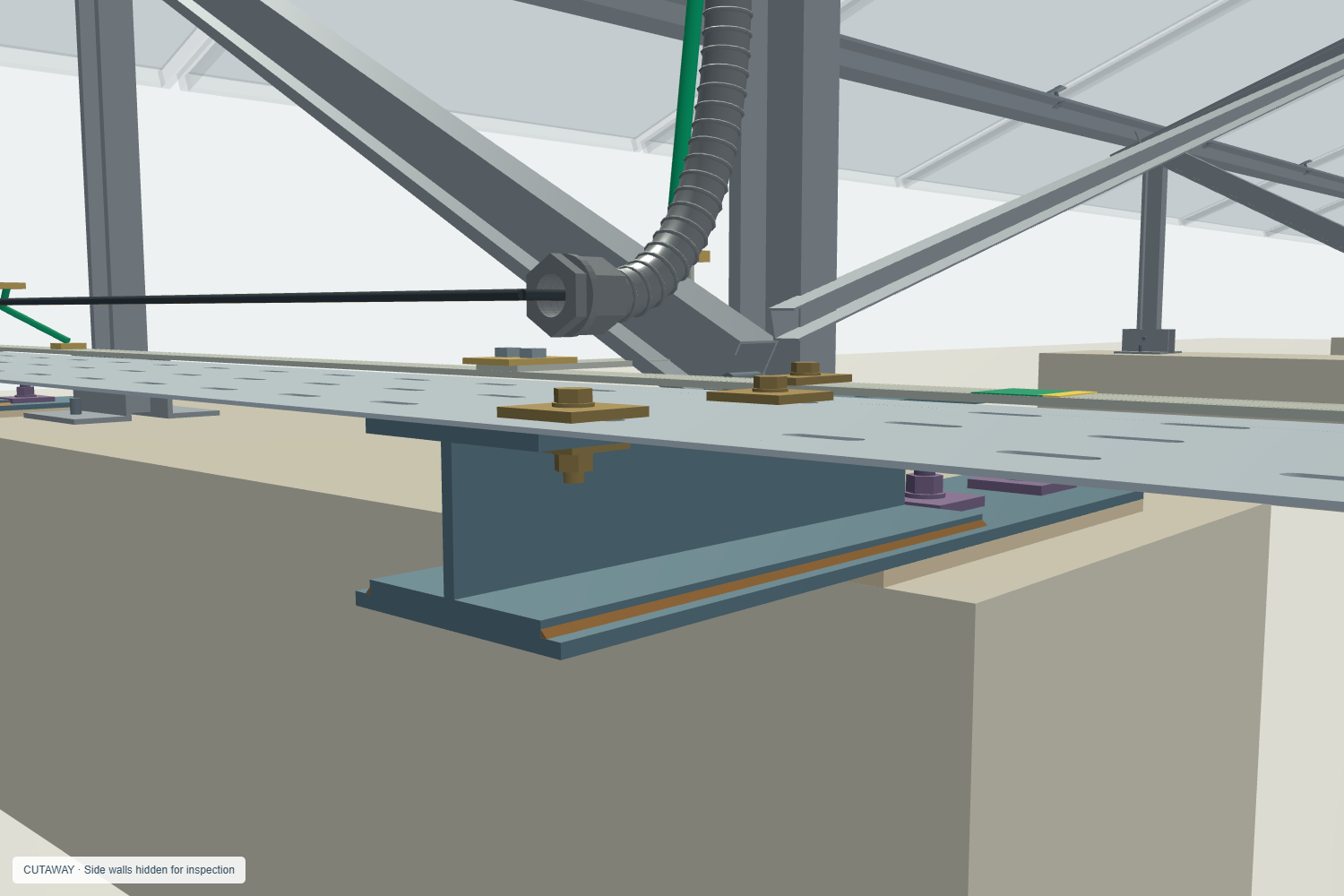
The independent-support node now includes actual bottom perforations. Use “Open tray lid / see bottom holes” to inspect the dedicated fixing slots and auxiliary holes. Silver and purple anchors have the same proposed geometry; colour identifies use only.
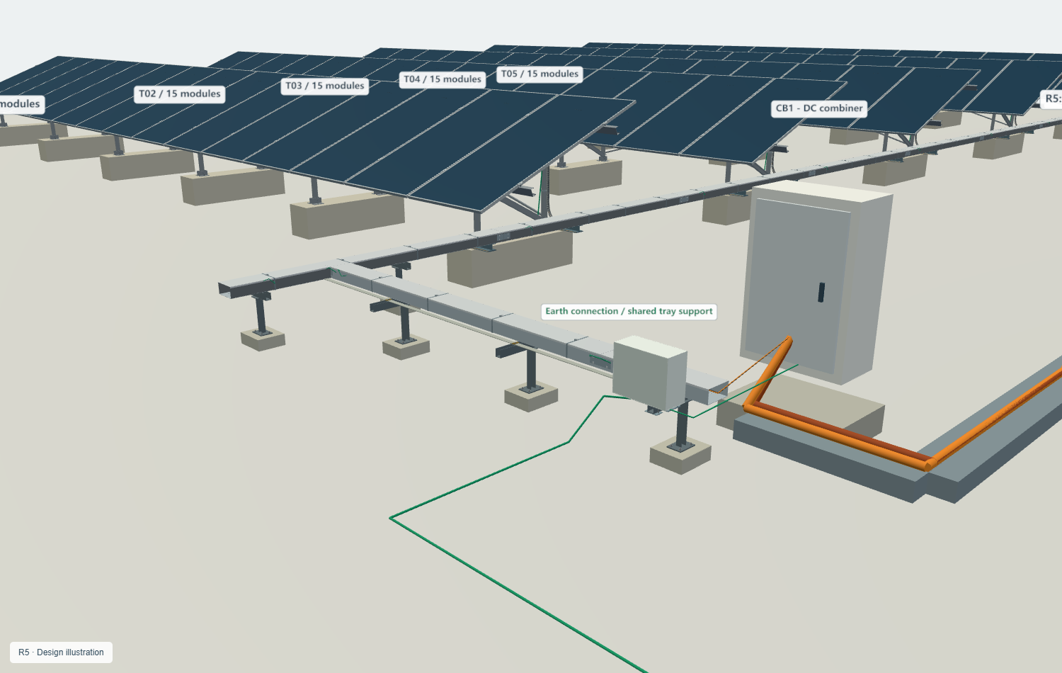
The bonding strip now follows the cross-tray supports, and the earth connection box mounts on the final crossarm. Three dedicated earth-return posts and their foundations are removed from the proposal.
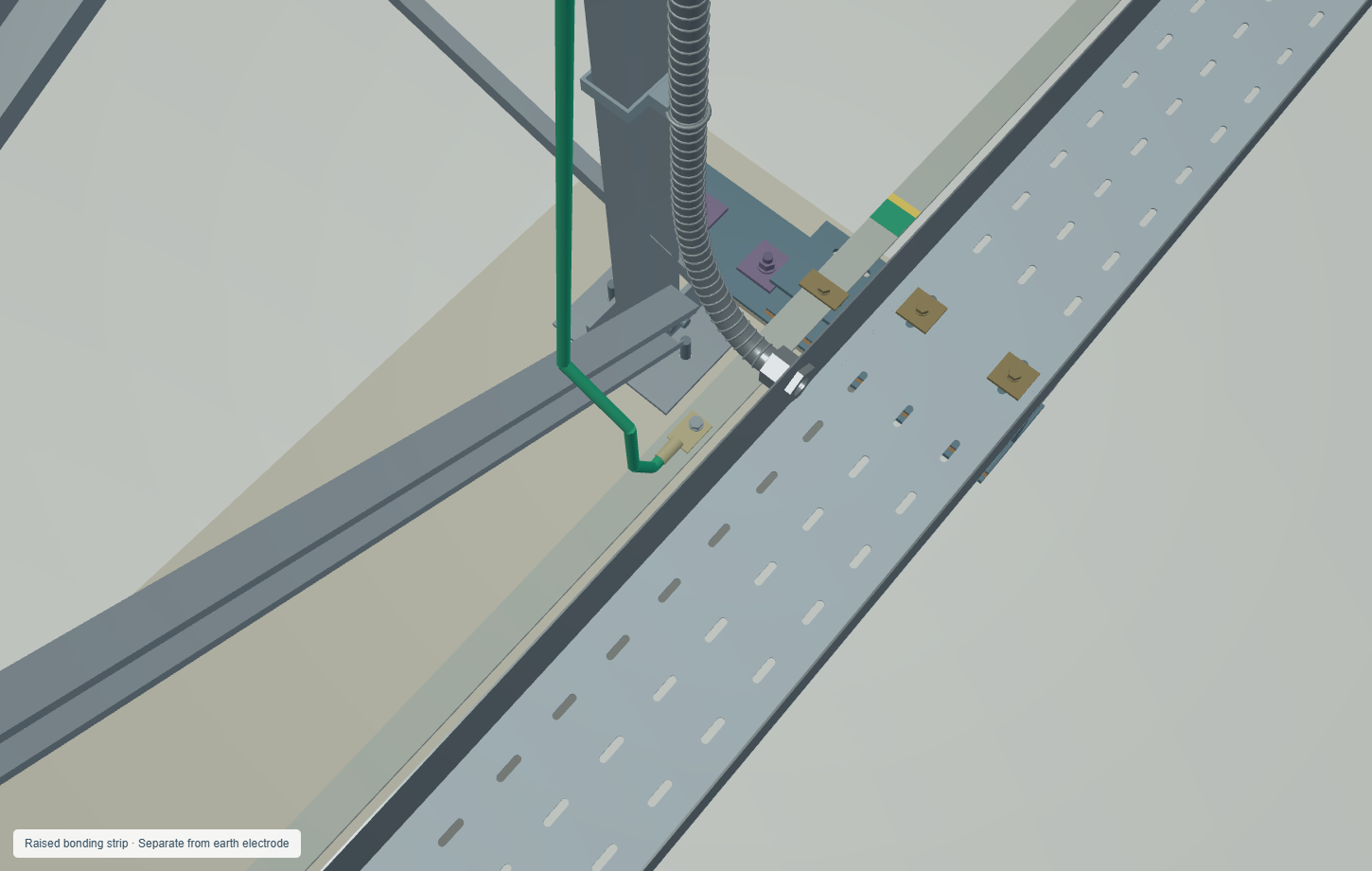
Row earth lead → crimp lug → common flat strip. The intermediate right-angle plate is removed. Each row uses one direct lug and one fixing set. This updates the visual proposal; terminal material compatibility and electrical sizing remain to be confirmed.
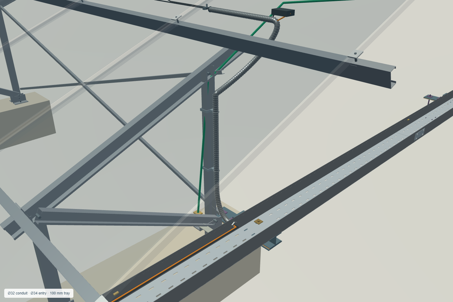
Proposed tray 200 × 100 × 2 mm, floor elevation 484 mm. Five Ø34 mm side entries are centred at 534 mm. OD32 mm conduit and OD46 mm fitting envelopes leave 30 mm vertical conduit-to-strip clearance and 16 mm fitting-to-cover-lip elevation clearance. The 40 × 4 mm bonding strip runs alongside, with 35 mm horizontal separation from the tray. Each row earth lead now terminates through one bolted crimp lug directly on the common strip. Five bent branch strips and their separate lap clamps are removed. Lug barrel centres are set 143 mm along the route from conduit entries; final lug material and barrel size must match the conductor and strip.
Dedicated 50 × 10 mm longitudinal tray slots cross the transverse I-arm slots. M8 × 30 bolts, upper spreader plates and lower plate washers are included. The original R5 ±15 mm cross/longitudinal fit trial remains. Smaller 30 × 8 mm auxiliary perforations avoid the main clamp zones. Cover bands remain separate from tray-to-support fasteners. The Bottom fixing view hides the walls for inspection only.
30 existing PV plinths; 10 independent welded supports and 10 additional cast-in U anchors on five end plinths; 20 tray fixing sets; 10 strip fixing sets; 5 conduits with 10 post clamps and 5 entry kits. Short cabinet-approach sections retain 5 tray supports. The cross-route bonding strip shares three of these supports, and the earth connection box is clamped to the final tray crossarm. No separate earth-return posts or foundations are added. Illustrated main/combiner tray centreline length: 26.575 m, without waste allowance.
The revised connection passes 97 fit checks; both updated STEP models were inspected and rendered. The 3213 mm cross-row support span, tray load capacity, anchors, concrete, welds, levelling and thermal movement remain unapproved. Module wiring and clips are illustrative and require the selected module lead configuration and electrical checks. The wellhead route is retained context, outside this update. Earlier revisions are retained in the local archive and hidden from the current customer-facing view.
Return to the interactive project